For work mode 1
(Cell phones carry on the WiFi module directly.)
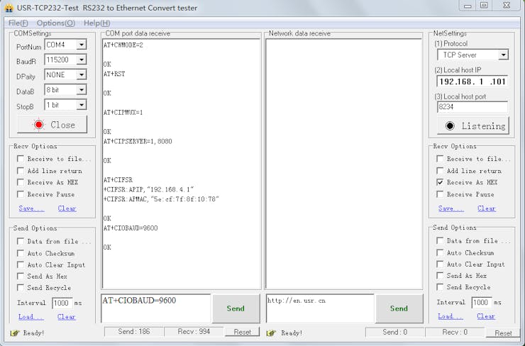
Open the “USR-TCP232-Test-V1.3” serial debugging software on the PC, send the following commands step by step:
- AT+CWMODE=2, select AP mode;
- AT+RST, reset;
- AT+CIPMUX=1, open multiple connections;
- AT+CIPSERVER=1,8080, configure the TCP server, set the port number;
- AT+CIFSR, view the IP address in AP mode, such as: APIP, “192.168.4.1″;
- AT+CIOBAUD=9600, set Baud rate to 9600.
- Connect to the AP (Access Point) of ESP8266 WiFi module on an Android cell phone.

- Install the “EasyTCP_20” app on the Android cell phone and open it; click “connect” and enter the IP address and port.


- Press the function blocks and enter the name and content of the serial command (A00101A2 open relay, A00100A1 closed relay, command format must be hex).

1 / 2
- Finally you can send serial commands to control the relay by clicking the function blocks.

For work mode 2
(Cell phone and WiFi module carry on the same router.)
Open the “USR-TCP232-Test-V1.3” serial debugging software on the PC, send the following commands step by step:
- AT+CWMODE=1, select STA mode;
- AT+RST, reset;
- AT+CWJAP=<ssid>, <password>, let WiFi module connect to the router, for example: AT+CWJAP=”LCTECH”,”12345678″;
- AT+CIPMUX=1, open multiple connections;
- AT+CIPSERVER=1,8080, configure the TCP server, set the port number;
- AT+CIFSR, view the IP address in STA mode, such as: STAIP, “192.168.1.103”;
- AT+CIOBAUD=9600, set Baud rate to 9600.

- Using cell phone connect to the router.

- Install the “EasyTCP_20” app on the Android cell phone and open it; click “connect” and enter the IP address and port.

1 / 2
- Press the function blocks and enter the name and content of the serial command (A00101A2 open relay, A00100A1 closed relay, command format must be hex).

1 / 2
- Finally you can send serial commands to control the relay by clicking the function blocks.

Kind Reminder:
1. WiFi relay module need to reconfigure if restarted.
2. ESP8266 WiFi module has a timeout mechanism; when the cell phone hasn’t sent commands to the ESP8266 WiFi module over a period of time (default is 180s), the ESP8266 WiFi module will kick off your cell phone. So you can send AT + CIPSTO = < time > on the PC to modify this time (time range 0-7200), such as: AT + CIPSTO = 3600 .
3. If it does not return OK and just returns what commands you’ve sent when you use “USR-TCP232-Test-V1.3,” configure the WiFi module. You can press ENTER before sending commands.
4. If it has no response when you use “USR-TCP232-Test-V1.3,” configure the WiFi module, maybe the baud rate is incorrect. You can try 115200 or 9600. But when you use cell phone to control the relay, you must make sure the baud rate of WiFi module is 9600 (send AT+CIOBAUD=9600 can change it), because the baud rate of onboard MCU STC15F104W) is 9600.
5. If you want to use a computer to control the relay directly (baud rate is 9600), you can: unplug the ESP8266 WiFi module; and TX ,RX & GND pins of USB to TTL module connect to TX ,RX & GND pins of WiFi relay module; and IN+ and IN- connect to DC5V power. Send serial commands (A00101A2 open relay; A00100A1 closed relay, command format must be hex) with serial debugging software on the PC to control the relay.
6. If the relay can’t open or close, maybe you need remove the R4, and use the USB to TTL module’s VCC pin connect to relay module’s 5V pin.


İlk Yorumu Siz Yapın